To:beam@palladium.corp.sgi.com
At 4:46 PM -0700 10/13/98, Mark Fedasiuk~ wrote:
:
:...
:
:Then I decided to get a bit fancier and wanted my bot to slowly avoid
:collisions before it got there. ... I
:decided to accumulate non-hits. So my counter would start at 0 and
:for every non-hit it would add 1. When it was done with this loop,
:if it remained 0 that mean I had all 5 0's and detected a collision like
:before, but now I have a number of 1-5 which showed me how many non-hits
:I had.
:
:When I was playing with this, I discovered that this was almost a perfect
:RANGE detector for my hand! As I moved my hand closer, the counter would
:read 5,4,3,2,1,0 in about 6 inch increments and had very reliable and
:repeatable results! I was stunned as I did not exptect such linear and
:repeatable results based on what I say on the scope. None the less
:it worked like a charm!
:
:...
:
:Since this is a beam list, anyone care to venture an idea on how to
:BEAM this concept?
:
:mark
Just food for thought:
First off, you've got to control sampling in a BEAMlike manner. Probably
the cleanest (though not absolutely minimal) way of doing this would be to
use the output of one neuron of a bicore as your "clock" -- this way it
would be relatively easy to control the on time and the off time with the
time constants of the two neurons. This signal would control both the
enable of the signal going into the output LED as well as gating the output
of the detector into a simple neuron chain.
What you'd want here is something that is similar to a single leg control
circuit in the patent. You connect, say, five or ten "everyday" Nv neurons
in a simple chain. At sample time, the gating circuit (left as an exercise
for the student
beginning of the chain or it wouldn't. One presumes that if a single
process is put into the chain, it eventually "falls off" of the other end.
If lots of processes are put into the chain, it would quickly saturate.
In any of the possible cases, you could buffer all of the outputs of the
chain into a summing circuit. If all you want is a binary response, a
digital inverter could be used as a threshold device, but you'd lose that
nice range detection you wanted. If you want the range detection, you'd
just have to find a way to use analog output of the summing circuit (which
could be as simple as a bunch of resistors & perhaps diodes. Again, an
exercise left to the student.)
You'd probably want to smooth either the outputs of the chain or the output
of the summing circuit with some kind of integrator. Again, you could use
an Nu type neuron (which still has a digital inverter as its active
element) to do this, but it would only provide binary signals - i.e. "I saw
something important enough recently". This smoothing would be important
'cuz you'd want the information flow to match the nervous net which is
moving relatively slowly (to control walking, f'r'nstance.)
A rough diagram:


                      Bicore --------> LED driver
                        |
                        |
                        |
                        v
    IR Detector ------>Gate ----->Nv--->Nv--->Nv--->Nv--->Nv
                                   |     |___  |    _|     |
                                   |         \ |   /       |
                                    -------> Summer <------
                                               |
                                               |  Analog "sum" of recent hits
                                               |
                                               v
                                            Smoother   (if needed)
                                               |
                                               |
                                               |
                                               v

                  To rest of the nervous net, probably an excitation or
                       inhibition input of a Nv neuron.
You might want to weight the inputs from the Nv chain -- the most recent
being the most important or something; each succeeding gate having less
weight so that it acts like a decay curve. It would certainly be something
to play around with.
Have fun with the idea.
Zoz
Subject: A distinction between Convergence and Balance, pt.1
Date: Fri, 28 Aug 1998 18:26:47 PDT
From: "Tom Edwards"
To: beam@palladium.corp.sgi.com
I used to go to seminars that supposedly were designed to help people
understand the sea of language they were swimming in without even
knowing that was where they were. After all, a fish doesn't really pay
any attention to water and birds don't concentrate on the concept "air"
but they seem to do pretty well. Language is where we often find
ourselves floundering and not knowing why.
Now, you are warned not to try to believe anything that I write here -
I'm not promising that any of it is the truth. Merely try out these
ideas like they were clothing and see if they fit.
If I were back in one of those seminars, the first thing we'd do after
the usual administrivia & glad-handing was a fairly intense
brainstorming session. One one whiteboard they'd put up one idea... say
"Convergence" and on the other another idea... say "Balance". At first
we'd be challenged to come up with all of the statements that we "knew"
about these things. For example, "convergence is when the three color
guns in your TV are lined up so that the resulting colors on the screen
look right" or "convergence is when two things get closer and closer."
And then, "balance is something I lose when I drink too much; as a
result I fall down when I drink" or "a balance between income and
expenditure is the very least you have to have to avoid debt." We would
go at this for 45 minutes and take a break.
After the break, we'd do the same thing except that we'd use negatives.
In this case, one statement might be "if you don't achieve convergence
of the time constants of a microcore, your walker doesn't walk very
well" and "a walker seems to lose its balance if the microcore isn't in
convergence and then that robot flounders around."
Our homework would be to presume that we hadn't really answered the
questions of "what it is" and "what it isn't" about the distinction in
question. Since we can't really do much of a true brainstorming session
here ( a- this forum is too slow, b- we tend to think we "have the
answer" too quickly in this forum) I reckon that replies to this message
could be more like the homework I used to do -- say, further statements
about the distinction between "Convergence" and "Balance." It might be
fun for you to do this. I think that you'll find yourself having to be
fairly brave to post your ideas. Whatever.
Now, down to brass tacks. I'm not going to name the authors of the
following statements because ownership isn't what matters. I'm also
going to paraphrase what they wrote slightly, but I don't think that it
will insult the authors, and it might help us maneuver around the
concepts a little bit better. Again, this all may be complete B.S., but
try it on anyhow.
Balance is...
achieved when the values of all the resistor and capacitor
component values of a microcore are matched up perfectly.
is possible to achieve using pots to compensate for drift. (Um,
if you really believe this, try to get Tilden to send you one
of his "pot burner" buttons that he gives to some people at a
summer seminar in Colorado.)
dependent on the design of a robot: for example, the center of
gravity, the stresses on the legs and the relation between
the two.
something that you can tune.
Balance is not...
something that can be nailed down to only one source.
something that can ever be achieved perfectly.
something that real devices, like motors, ever tend to have.
possible when there are differences in the friction of various
mechanical components.
Now, here are a few of my own:
The term "balance" is only usefully applicable to a robot's
mechanical structure.
Balance depends on the center of gravity and how it relates to
the vectors of support as defined by the leg structures.
Attempting to "balance" a microcore is a frustrating, futile
exercise because it is essentially impossible to measure the
nonlinearities of the inverters used. Furthermore, even if
you knew those values precisely, you'd still by stymied because
such a system is basically chaotic -- it can be predicted in
the short run but will show wide variations (in this case,
leg drift) in the long run.
If "feedback" is a reality and is valuable to the competence
of the robot, then every difference from the nervous net neurons
through their drivers to the motors to the mechanically driven
components all the way to where the feet touch the ground is
going to cause, in the small, unpredictable "forces" to the
functioning of the microcore, making it even more nonlinear.
In the large, however, a big force on a leg is going to
produce a _predictable_ source of feedback to the loop that is
presumed to be much larger than the usual small sources of
unpredictability. The conclusion of this statement is that
"balance" (like trying to get all of the neurons to fire for
precisely the same amount of time as each other and forever)
just isn't going to happen and you wouldn't want it.
Well, that's gotten pretty thick. Time to take a break. Save this
email, put it away for further thought. The next note will be a
little bit of brainstorming about the concept of "Convergence." As
you may have gathered above, however, it is possible that what I might
be writing is that convergence is going to depend directly on fairly
definite IMBALANCES with regard to the microcore (something that was
alluded to but not directly stated by Dennison.)
T
Re: My Education:uP? I kinda Agree.
Mark W. Tilden (mwtilden@aerie.lanl.gov)
Fri, 15 Aug 1997 12:55:33 -0700
>On Fri, 15 Aug 1997, Dennlill wrote:
>> You know, when you think about it a huge net of Nv's could work like a
>> Processor. SOMEONE out there should design a chip with the solar engin
>> circuitry and/ or walker circuitry built in, and then do some heavy
>> intergration. You could pull some need behaviors out of a chip with some
>> sort of implementation of 10,000 transitors!
Just what was hoped, but as some may be finding out now, homogeneous Nv
systems loose phase competency at large integration scales. That is,
adding an active head or other form of controller to a walking body and
keeping it competent is not as trivial as it sounds, and the problem gets
worse the more diversity levels one adds.
One of the big projects i've been working on for a few years now is how to
structure such larger Nv arrays to optimize function instead of disco. One
solution is symetric, folded, bidirectional control architectures and the
Strider robot (Dave H's page) is one of the first successful walking
implementations. Larger Nv forms are in the Wave Processor boards now
running in my lab (100 plus neurons) and the folded "Rubics brain"
prototypes, which are literally broad-stimulus parallel integration
processors waiting for bodies complex/large enough to support them (such
bodies under development now if I can scrounge motors powerful enough to
drive them).
So large scale Nv structures are possible, and the behaviors exotic, but
more experiment and analysis needs to be done before a 10,000 transistor Nv
'cortex' chip can be built, assumed useful, and plopped into a 'bots "head".
If this works, it should be some seriously impressive shit. I'll be
impressed anyway.
Details pending.
markt.
Re: VBUG 1.5 Walkman and Nu neurons
John A. deVries II (zozzles@lanl.gov)
Sat, 12 Jul 1997 00:59:14 -0600
At 02:23 PM 7/10/97 -0400, Andrew Miller wrote:
>A practical difference is that Nv and Nu neurons are laid out a bit
>different...
>Basically swap the resistor and the capacitor so you have resistors running
>between output and input and capacitorss tied to ground...
>Along with the original topology it gives you an integrator and a
>differentiator....
>Combinations of the two give higher function (but are a bitch to
>tweek)...
Mostly true, Andrew-san, very good explanation...
>A semantic diference is that "living machines" was written 2� years ago
>and definitions have been redefined...
Well, sort of.
>The idea of calling MicroCore tech a "neural" net has been drop since we
>managed to show that "Nervous net tech" is all that is needed when
>describing these things....
Without giving too much of it away, the really farkling amazing (and by the
way, I'm not kidding on this one newbies, and small gods alike) UniCore
structure really -does- use Nu (integrative-style) neurons (and NOT just as
power-up delay circuits) combined in a connectionist manner with Nv
(differentiator-style) neurons. I'm doing my best to document what Mr.
Tilden has produced lately (and, in fact, proved to myself that the circuit
diagram he gave me two weeks ago or so really is just what he says it is
today rather than listen to the boring meeting I was in) but this involves
a process unlike what you robot-builders do. When I get enough down on
paper about this stuff, I'm going to beg Mark day and night to stick his
name on first and get the info published... In the mean time, anyone who
bugs him about it other than those who knew him before I did can expect to
get a mailbox full of whining and crabbing and saying "you could've bugged
me instead...."
>We've found using terms like "Master" and "Slave" more accuratly reflect
>the separations in Nv tech....
Just a little food for thought: say you did have two different Nv nets,
each doing their own oscillatory thing. You can slave one of them to the
other by putting a wire between the output of any gate on the master net
and connecting it to the input of any gate on the slave net (in fact,
bypassing the usual differentiating capacitor.) Well, that's cool and all,
but it is kind of permanent, at least the way we've been doing things so
far - it is a wire soldered in or a resistor stuck in a socket or
something. More importantly at this point is that if those two individual
nets each contributed just one behavior to the overall _being_ of a
biomorph then such a connection would quite simply and literally multiply
the spaces of the two behaviors: and as we've read in stuff that Mark has
written already, this often leads to not only unexpected, unpredictable
emergent behaviors, but _useful_ behaviors as well.
So, that's spiffy, but what I've heard an awful lot of conversation on this
mailing list about has been "can I put a PIC/BASIC Stamp onto a BEAM
device"? The really big question, a hugely fundamental and philosophical
question is: why the heck would you want to do so? Oh sure, you can make a
Stamp BEAM robot of some sort and you might come up with some interesting
results but it is hardly new (the Stiquito is HOW old?)
The really neat thing to think about is this: say you've got these various
nervous nets and each net shows extremely robust and capable behavior
within some portion of your problem space (i.e. seeing, navigation,
locomotion, coordination: all problems, the space is an n-tuple of them.)
And you've got this spiffy PIC or BASIC Stamp that you can use to implement
decision trees or fuzzy logic or what-have-you. And you've got something
like the '240 buffer which allows you to enable or disable four lines all
at once (tristate at that.) That means that your Stamp can say: "Since I'm
in thus-and-such a condition, I think that this particular behavior-set is
called for." It then connects up the nervous nets appropriately which then
do their thing efficiently and smoothly -- and don't even really need any
supervision by the Stamp. Wow. A non-linear increase in ability with
merely a linear increase of complexity.
How "smart", how a "robust" is your biomorph now? Perhaps you don't even
-need- to turn on the Stamp all that often.
Any ideas? Kudos? Brickbats? Tomatos?
Zoz
Subject:Re: HBS SE help me...
Date:Thu, 14 Jan 1999 18:01:21 -0700
From:Dave Hrynkiw
To:Evan Dudzik
At 06:13 PM 1/11/99 , Evan Dudzik wrote:
>i want more info on a happy birthday singer solarengine. i want to
>make one, but cant find ANY info ANYWHERE. can someone help me???
Well, the HBS we used for these controllers is no longer available. It was
the original Hallmark singing card chip, which we picked up in surplus. But
if you're still interested, here's the particulars as described by Mark Tilden:
"The happy-birthday singer is a two bit wide by n words deep programable
sequencer with 4 commands: reset to start vector (00), decrease frequency
(01),increase frequency (10), and pause (11). The device starts out with a
2 word vector jump at the start of memory which locates 16 positions in
it's memory. This jump vector is readdressed whenever a (11) command is
found in the execution table. "Happy Birthday" is the first in this chain
and is at default (00-00). There are at least 6 songs already in the
device which can be found by reprogramming the jump vectors. The vector
locations seem to be at either 256 or 512 bit increments in a 4k or 8k
memory map. These songs include "you light up my life", and xmas carols.
Reprogramming the singers is not simple in either process or technology,
and truth to tell I never completed my studies of the devices as it's a
bugger working with an already burned-in prom. The only details solaroller
builders need know are:
                   --------------------------------
                   |  Vcc   |     switch          |
                   |        |                     |
                   |---------                     |
                   |    |      gnd                |
                   |   ***  __________            |
              clock|--**uP*-|                     |
            whisker|  *****                       |
                   |   ***                        |
                   |   / \          Battery Holder|
                   |  |   |         (Usually cut  |
                   | [ ] [ ]         off)         |
                   --------------------------------
                  Quad outputs
- Soldering a cap between the thin clock whisker and Vcc gives an
approximate ratio of 1sec period = .1uF.
- Device operates from .98v to 5v with a significant current drain
happening around 3.1v (approx 3ma nominal). Device works optimally from
1.2v to 2.3v. A short of the power pins will reset the device but the
device has a power down mode between .3 and .98v where it will keep it's
internal count position without resetting. The input impedance of the
clock whisker is very high, and is obviously a direct link to the internal
resistor-cap junction of the internal oscillator. This pin has the classic
cap charge-discharge curve when probed. Resistors to this pin will also
work, but at a significant current increase for low power applications.
- Operating current of the device at 1.5v is in the microamps with the
piezo removed.
- The outputs are rail to rail drivers at about 2-3ma per transition. The
outputs are quadrature encoded, so they are always opposite polarity to
each other. They can be direct shorted for long periods without affecting
the device and handle positive and negative current spikes well.
- The only way of destroying them under nominal conditions is to power them
up backwards. They die very quietly and then only way to test is by
reattaching the piezo xtal to hear if the oscillator has stopped. Another
fault is when the cap soldered to the whisker is not superglued down after
being attached. There is no cure for this as the whisker is usually lifted
right from the pcb. Replace the device with another one."
To turn the HBS into a controller for a dual-solarengined photovore, use
the following technique:
Tie each separate solarengine trigger switch to each of the HBS outputs,
you can get alternating motions going. Mark Tilden uses this technique in
his BEAMants, which are layed out with two motor output shafts as "legs",
and a third "dead leg" to maintain balance. As the motors trigger, the
effect is that the BEAMant "walks" left-right-left-right on the motor
shafts. By adding a pair of hair-trigger switches to the front of the
beast, you can inhibit the trigger signal reaching the other-side motor.
So if it bumps into a wall on it's right side, the sensor inhibits any
further "triggers" to the left side motor, so it then pivots about it and
walks away from the obstacle. Just shorting the trigger lead to positive
will keep that circuit from triggering.
Have fun, Dave
---------------------------------------------------------------
"Um, no - that's H,R,Y,N,K,I,W. No, not K,I,U,U, K,I,_W_. Yes,
that's right. Yes, I know it looks like "HOCKYRINK." Yup, only
2 vowels. Pronounciation? _SMITH_".
http://www.solarbotics.com
Subject:Re: VORE N MORE... help me.
Date:Wed, 10 Feb 1999 21:52:36 -0800
From:Bob Shannon
Organization:Fair at best
To:Evan Dudzik
CC:beam@corp.sgi.com
Evan Dudzik wrote:
>
> Help me... I came up with a sort-of schematic for VORE N MORE but i
> cant seem to figure out how to integrate the the light sensor so it
> knows when the light is too low to go on and starts using the power
> from the large cap to run really fast towards a new light.
> can anyone help me? i have the cap and everthing, all i need is the
> light sensor that actually lets the cap discharge to the rest of the
> circuit.

Wow, this is the second request for Vore-n-More info is less than 20
minutes.

And my bots are not even on the BEAM web ring!

Vore-n-more uses a Radio Shack NPN phototransistor.  It looks like a
large, clear LED with two leads.

I call this circuit the Smart Capacitor, as it will slow or stop the
photovore (which should be near light, right?) to recharge the
supercapacitor energy reserve.  Then, when it gets dark, this stored
energy reserve is fed into the photovores main drive capactiors for a
burst of high speed movement towards another source of light.

It really works quite well, and I have had several requests for the
circuit.  Here it is:

Start with a normal photopopper photovore.  It should have a largish
solar cell, like a 3733, or a pair of 2224 cells from Solarbotics.

You will need to add (to plan ahead for this):

A 'floater' solar cell(s), another 2224, or a pair of Sanyo AM-1437
cells (as in the original Vore-N-More) wired in PARALLEL.

A 1N5817 Schottkey diode (do not substitue non-shottkeys here).

A Panasonic Gold Series super capacitor, I used 1.5 Farads, a larger cap
will cause a hungery Vore-n-more to sleep longer in the sun, and run
longer in the dark.  Smaller values will give shorter sleep and burst
mode times of course.

A NPN phototransistor (like the Radio Shack part I used).  This should
be a two lead type, or cut off the base lead from a three lead device,
just so electrostatic charges dont cause odd behaviors.

A 5.1 K resistor.  I used 1/16 watt devices to 'hide' them in the main
drive capacitor banks wiring.  This value sets the darkness detection
threshold, and may vary if you use a different phototransistor.

A PNP switch transistor, like a 2N3906

A discharge rate control capacitor.  I used 75 ohms.  This will set the
burst mode discharge rate, how fast your Vore-n-more will move when its
running from the super capacitor.

If this value is too low, your Vore-n-more will lock up, and spin in
circles when the lights go out. (maybe you like this?)  If its too high,
your photovores SE's may never fire.

(Random Tip - For the photovore's drive capacitor, I often like to use
an array of smaller capactiors wired in parallel rather than a single,
larger value cap. This way all their series resistances are in parallel,
making a 'more efficient' main drive capacitor. Its also possible to
arange the main drive capacitor around the rest of the photovore, rather
than the other way around, see the Eat at Joe's photovore to see this
trick in a different form.)

How does it get hooked together?

Its so simple, you'll kick yourself once you get it.

Run a wire from the positive side of your solar cell, to the negative
lead of your 'floater' cell(s). This puts your floater cell in series
with the main solar cell.

But your not supposed to connect solar cells in series, right?

Well, sometimes.  I'll get to that later...

Connect the positive side of the floater cell(s) to the anode of the
schottkey diode.  The cathode of the diode connects to the positive side
of the super capacitor.  The negative side of the super capacitor is
connected to the photovores ground connection.

Next, we make a voltage divider circuit with the phototransistor and
5.1K bias resistor.  The collector of the NPN phototransistor is
connected to the positive side of the super capacitor.  The emitter goes
to the 5.1K resistor.  The remaining lead of the 5.1K resistor goes to
the main photovore ground (negative side of the main drive caps).

Next, we add the PNP switch transistor.  The PNP's emitter goes to the
collector of the phototransistor.  The base of hte PNP connects to the
emitter of the NPN phototransistor.

(I mounted this transistor right onto the NPN phototransistor by
notching out the clear plastic and gluing the PNP transistor into the
notch.  You can sorta see thin in the guts view photos.)

The collector lead is the output of the smart capacitor circuit.
You can connect this to any small device you wish to operate, like a
LM3909 LED flasher.

To drive the photovore with the output, we connect a 75 ohm resistor
from the collector of the PNP switch to the positive side of the
photovore's main drive capacitor.  You may want slower bursts, and may
get away with faster ones as well, by experimenting with the value of
this resistor.

So how does it work?

First, lets assume that Vore-n-more has zero power.  Its dark, so
nothing happens, and we are asleep.

When the sun rises, the super capacitor acts like a dead short, and
prevents the photovore from moving. We are now in feeding mode.
The super capacitor voltage slowly begins to rise.

Once the super capacitor voltage rises above 2.5 volts or so, the
photovore begins to wake up, and seek light normally.  We are awake.

The voltage from the photovores main solar array is now changing,
charging up for each step.  The floater solar cell takes this changing
voltage, and adds to that, so we are using a peak charging voltage that
is higher than the trigger voltage of the solar engines.

The schottkey diode prevents the super cap from discharging through the
solar cells in the dark.  We must use a schottkey to keep the voltage
drop across the diode very low.

This is critical, we must charge the supercapacitor to a voltage higher
than the SE's trigger point.  For 1381-J triggers, a good 'fully
charged' voltage would be around 3 volts.  Once we reach this point, we
are ready for burst mode behavior.

Light falling on the NPN phototransistor holds the transistor in a state
where is starves the PNP switch transistor off.  As the light level
falls, the phototransistor will switch off (at a point set by the 5.1K
bias resistor).  This in turn switches the PNP transistor on.

Now we are in burst mode.  The light level has fallen, and the switch is
on.  The super capacitor begins to discharge through the switch
transistor and the 75 ohm discharge rate resistor.  The power is used to
drive the photovore.  With 75 ohms, it will move FAST, and still be
highly phototropic.  The photovore will lock onto a dim, distant light
source in another room, and track it perfectly.

Your Vore-n-more will also move for quite a distance in a burst.  With a
1.5 farad cap, you will get several dozen of steps per charge.

This circuit can be used to drive a photovore, or even a Turbot (right
Dave?), perhaps even a solarized walker as well.  It can drive SE's,
microcores, and bicores.

I've even used it to power up a PIC when it gets dark.

On my beam robot site, you will also see a Symet (Triluminary) that
carries around a smart capacitor circuit and a LM 3909 LED flasher, so
it blinks away (for about half an hour on a 1.5 farad cap) when it gets
dark and stops moving.  In this robot, the solar cell that charges the
super capacitor is not connected to the drive capacitors in any way, yet
the two system still interact perfectly.

One list reader has already made a .GIF (or .JPG ?) file that shows the
basic circuit.  The interconnection of the basic smart capacitor curcuit
and the photopopper should be fairly clear in the description above.

I'll try to get a full diagram onto the web site soon.

I hope this gets some people playing with the circuit.  There are
several variations you can try:

Replace the PNP switch with a PNP darlington.

Replace the NPN phototransistor with a photodarlington.

Replace the floater cell and schottkey diode with a coin cell and series
resistor.  This is the 'smart socket' varient.  You can see this circuit
in the Symet Zaraam on the web site, where it flashes a LED just like in
Triluminary.

Enjoy, and let me have any questions if I've left out any important
details.
Subject:How to put your foot in your mouth...
Date:Wed, 09 Dec 1998 12:22:22 -0700
From:Jean auBois
To:beam@spindle.corp.sgi.com
Before everyone else points out my goof, I reckon I will:
"Normal" bicore: two plain Nv neurons connected in a loop. Resistors
connect to ground.
Suspended bicore: Similar to the "normal" case except (as a first step in
understanding) the two resistors are connected to each other. The point
where they connect is a virtual or "suspended" ground. Usually the two
resistors are replaced by one single one or a bunch of nonlinear sensor stuff.
Embedded bicore: Like it sounds, one bicore within another. In other
words, one of the bicores is the master & its outputs connect, via
resistors, to the bias points of the slave bicore. There is no single
resistor or sensors coupling the two opposite corner of the outer (slave)
loop: the inner (that is, embedded) bicore takes their place. The kind and
amount of effect the master bicore has on the slave depends strongly on the
values of the resistors that connect the two bicores.
Blushingly,
Zoz
Subject:SE / alf circuit variation..
Date:Fri, 16 Apr 1999 12:53:57 -0700
From:Darrell Johnson
To:beam@corp.sgi.com
ok.. I've been messing around with the SE part of the alf circuit, and think I might have an improvement:
Instead of the pulse generator and the series of diodes to trigger the latch, why not use a 1381 to start it. The 1381 only uses between 1 and 5 uA during operation, while getting rid of 2 resistors, a capacitor, and 4 diodes.. as well as freeing up 2 inverters on the 240.. (this is based on the bivore schematic by Justin Fisher)
I've attached a 2k .gif file of the circuit... Let me know what you think, as my electronics background is a bit shaky.. I have breadboarded it, and it *does* work, so it's not just a theory..
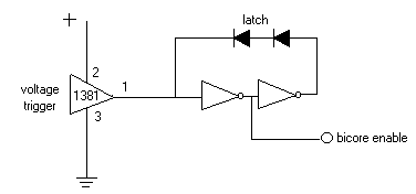
-darrell
Influential E-mails Page 3
BEAM stuff
Beam Table of Contents