Photovores


First off, if your new to BEAM and haven't had much experience with electronics, go to Solarbotics and buy the Photopopper 4.2 kit. It is an excellent kit with all the parts you'll need, a high output solarcell, new pager motors, omni-directional feeler switches, in-depth and informative documentation and a cute little PCB. It's well worth the money! Here's a couple pics to wet your appetite


The BEAM photovore is an autonomous robot that is entirely powered by solar energy. It is phototropic which means it searches out the brightest source of light which, in turn, gives it more power...pretty smart eh? The first step to building a photovore is to get the schematic.


Schematic posted with permission from Dave Hrynkiw.
If you want a full kit with all required parts, a very high quality PCB and circuitry for feeler switches, go to Solarbotics.


And a parts list...
2 X Panasonic 1381J 2.6V-2.9V Voltage detectors (digikey part # = MN1381-J-ND)
These voltage detectors come in many different voltage ratings. If your motor is spinning too hard, losing traction with the ground, you may want to use a 1381G (2.4V-2.6V) or 1381E (2.2V-2.4V). If you want more power per step you can use the 1381L (3.0V-3.3V) although it will take longer to charge up.

2 X Photodiodes (digikey part # = LT1032-ND)
I'm not positive on this part number. I got a big box of photodiodes for free so I haven't ordered these specific ones.

2 X .22uF capacitors (digikey part # = P4958-ND)

2 X 2N3904 NPN transistors (digikey part # = 2N3904-ND)

2 x 2N3906 PNP transistors (digikey part # = 2N3906-ND)

2 x 2.2K ohm resistors (digikey part # = 2.2KQTR-ND)

1 X 4700uF eletrolytic capacitor (digikey part # = P5118-ND)

1 X 100K ohm potentiometer (digikey part # = 3386H-104-ND)

2 X Pager motors or small tape recorder motors. They have to be efficient. I suggest the Solarbotics pager motors. The Namiki 1701.

2 X Fuse clips. Or any thing you can use as motor mounts. (digikey part # = FO52-ND)

1 X Solarcell. Any solarcell that can output atleast 3.5V will do. Solarbotics has the best high-current solarcells around.

Next I suggest you breadboard the circuit just so you know all your parts are good and my schematic is right! ;)


Test the circuit by approximately centering the potentiometer and throwing the circuit under a light. One of the motors should be spinning (popping). Cover one photodiode then the other with your finger. Do both motors spin? If alls good then you can build your photovore.

There are many ways you can build the photovore circuit. My favorite is free-forming.


First off, glue the two 1381's face to face. Then glue the two 3906's together and the two 3904's together and glue them all into one block. This block arrangement is ripped off from Paul Beckingham ;-) .


Make a ground loop. Solder together pin 3 on both 1381's and the Emitters on both 3904's. All four pins need to be connected together.


Now make a positive loop. Since the potentiometer wiper is connected to positive, now would be a good time to glue it to the photovore block. Solder the potentiometer wiper to the Emitters on the 3906's and leave a short length of lead hanging out the back. You'll need to solder other components to it later.


Now you can make some of the other connections. Solder pin 1 on the 1381 to the Collector of the 3906 and the Base of the 3904. Do the same on the other side.


Check back to the schematic often. If you make a mistake, it's very hard to correct.


It's time to give out little creature some eyes. These photodiodes were given to me for free. They work very well for BEAM applications. Your photodiodes may look very different. Make sure to figure out the photodiodes polarity. They won't work if installed backwards. Anode goes to the potentiometer leads and cathode goes to pin 2 on the 1381's.


Install the capacitors from the photodiodes cathode leads to the ground loop you make in the first step.


The completed brain. The 2.2K ohm resistors are installed from the Base of the 3906 to the Collector of the 3904 on both sides. Leave a length of lead on the side of the resistors that connects to the Collector (3904) to hook to your motors. These 2.2K resistors are for tuning the solar engines to perform it's best with your particular motors. Experiment for best results. Check for visible shorts and bad solder connections. You may want to clean off all the flux too.


All the components. Final assembly will start when I can find some fuse holders for motor mounts. That cute little 1000uF capacitor probably won't give hold enough juice but it's so small I have to try it out. The solarcell is a Panasonic Sunceram 22mm X 24mm and the pager motors are Namiki 1701's, both from Solarbotics.


For those of you that couldn't wait...here's the final steps. Solder the capacitors positive lead to the solarcells positive lead then solder the capacitors negative lead to the solarcells negative lead. A capacitors negative lead is labeled on the can with a minus sign and arrows to the negative lead. Now solder the positive connection to the red "positive" lead and the negative connection to the white "ground" lead (ground loop). Now, choose with motor is going to be on the right (iny, miny, miney, moe works well for me) and figure out the lead polarity. Red is positive and the dark color or white is usually negative. The right motors positive wire goes to the photovores red "positive" lead and the negative motor wire is soldered to the green "left" lead (confused yet?). The left motor is installed the same but flipped. The left motors positive wire goes to the blue "right" lead and the negative wire is connected to the red "positive" lead. Put the photovore under the closest desk lamp and it should take it's first steps. Photovores are rather slow and boring by themselves but if you build 3 or more, you'll be quite surprised by the little quarks and attitudes of each one.


Here's a graphical representation. The order of building was:

1 = Black
2 = Red
3 = Blue
4 = Green
5 = Brown
6 = Purple
7 = Orange
8 = Yellow


After leaving this progect hanging for a while I decided to finally make some motor mounts. The mounts are made from tubing found in my junk box that fit the pager motors perfectly.


As usual, my aesthetics are dreadful.


The yellow stuff on the motor shafts is heatshrink tube. I find this stuff makes the best feet. One of the things I like about this photovore is that it's solarcell is tilted forward. Since it will be heading towards the brightest source of light, it just makes sense. I plan on changing the cap and solarcell to larger units to increase activity. With the 2200uF cap, it charges very quickly but it's steps are very small.


The finished photovore. Set it up facing towards a 100W light bulb and he should start popping towards it. Use the potentiometer to make fine adjustments until he walks dirctly to the light. One of these days I'll detail touch sensors...one of these days...

Are you having trouble getting your photovore to work? Here's a great e-mail from Dave on trouble shooting.

Subject:Re: photovore...oh damn
Date:Wed, 10 Feb 1999 01:19:29 -0700
From:Dave Hrynkiw
To:beam@corp.sgi.com

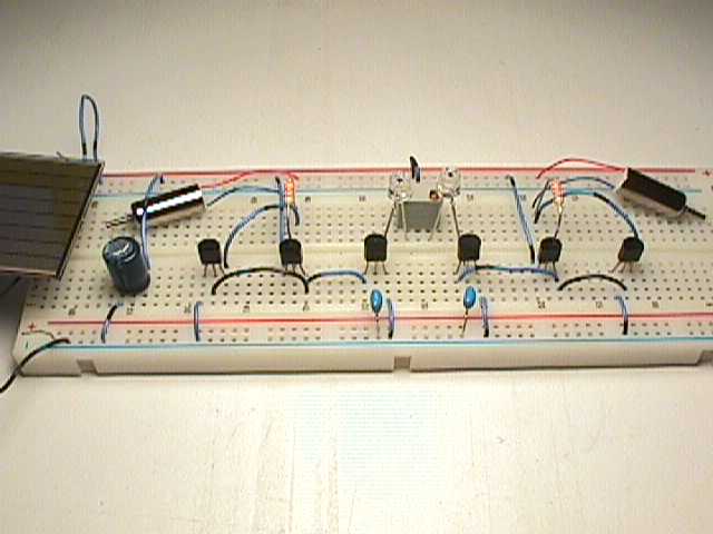
Lesson 101 on how to check your Photopopper:

Preamble: Before doing ANY of the following, sit down with your soldering iron and re-touch all the solder connections. We find that 90% of the returns to Solarbotics are fixed in under 30 seconds with nothing more than a soldering iron and some solder to fix bad solder joints. DO IT. Don't think "He can't mean _MY_ solder connections". Yup, I do. I have seen poor solder joints on every returned item from somebody who INSISTED that their soldering is perfect. Another thing - do not be quick to blame your problems on a faulty component. I have seen exactly 3 bad transistors _ever_. And NEVER a bad 1381. With that said, let's begin.

Step 1 - Preparation: Didja mount tactile (touch) sensors on it? Remove them. It cuts down on the complexity of the debugging task.

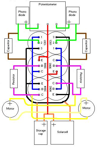
Step 2 - 1381 testing: If it is running in circles (as it most likely is), that indicates one side is obviously dead, or seriously mistuned. Crank your trimpot all one way - do you hear a slight buzzing? No? Crank it the other way. Still no buzzing? That means there's a problem with the circuitry to the 1381. Inspect your power and ground connections to the 1381.

If you hear buzzing, that means the 1381 is trying to trigger, but the solarengine isn't activating. No buzzing = no 1381 action.

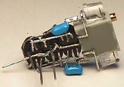
Step 2a - 1381 testing, part deux: Run a jumper from the Vcc (positive) of your main cap or solarcell to the middle leg of the suspect 1381. This will effectively bypass all sensory inputs, and FORCE that 1381 to be the one that will trigger, everytime. Does it work now? Check the IR photodiode - may be in backwards. Did you forget to install the cap for the 1381? Is the 1381 itself in backwards?

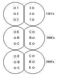
What, it still doesn't work? Even after checking that there's a positive voltage on the middle pin of the 1381, and ground to the right-side pin (viewed pins down, text/flat side facing you)? Hmm. Must be the solarengine

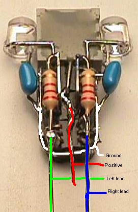
Step 3 - Solarengine testing: Run a wire from positive and _tap_ the middle leg pad of the 3904. Do this a few times while watching the motor. Does it make the motor spin? That's a good sign. Now notice carefully - does it spin a bit longer after you remove the wire? Good, that means the Solarengine portion of the circuit is working properly. If it only works while you are holding the wire to the middle (base) leg of the 3904, that means the circuit isn't latching, or staying on. Your 3906 should be inspected.

If you have not found your problem by now, start reinspecting your handiwork for obvious flaws like a blob of solder bridging solder pads, or improperly installed components. Did you use glue to install the electronics? Yes, I have seen this. It doesn't work. So don't do it.

Regards,
Dave
---------------------------------------------------------------
"Um, no - that's H,R,Y,N,K,I,W. No, not K,I,U,U, K,I,_W_.  Yes,
that's right. Yes, I know it looks like "HOCKYRINK." Yup, only
           2 vowels. Pronounciation? _SMITH_". 
                http://www.solarbotics.com


Reader's Photovore Successes

Please e-mail me. me if you have any questions or if you spot a mistake.
When your done your photovore, e-mail me a jpg and I'll post it for you.


Beam Table of Contents